
In the Spotlight


New Products
-
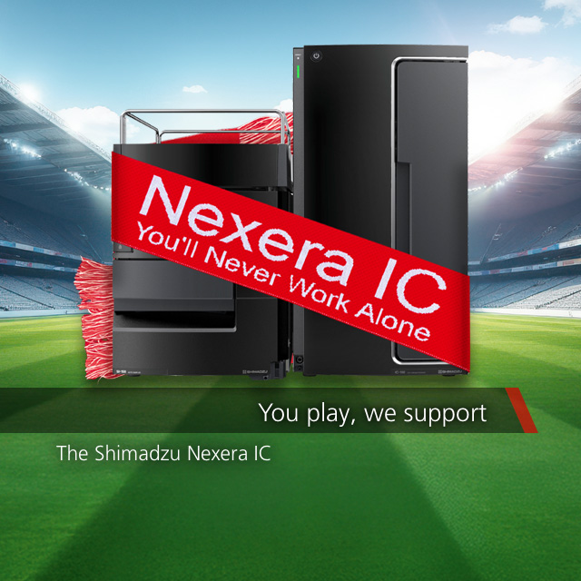
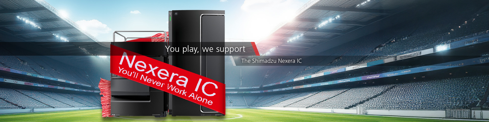
Nexera IC Ion Chromatograph
The Nexera IC ion chromatograph combines a compact footprint with uncompromising performance, enabling anyone to perform analysis effortlessly and efficiently.
-
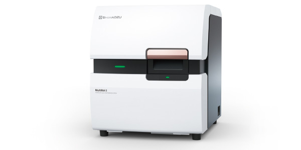
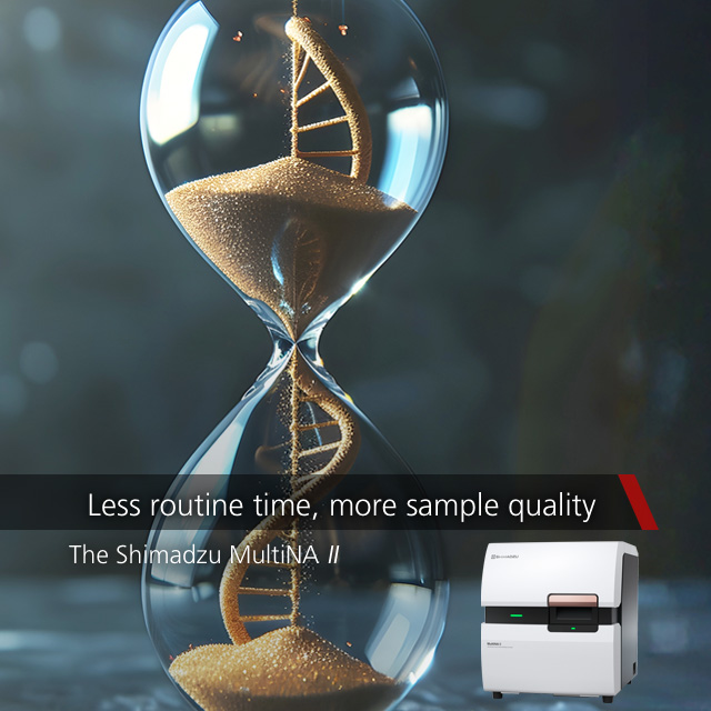
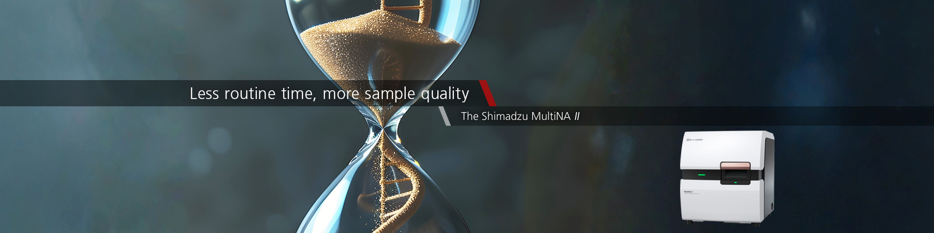
MultiNA II MCE-301
The MultiNA II MCE-301 is a microchip electrophoresis system for streamlines genetic analysis workflows by fully automating nucleic acid electrophoresis—a process that typically requires over two hours of manual work.
-
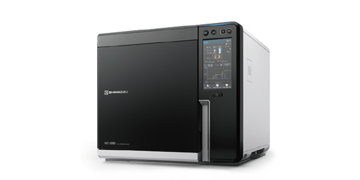
Nexis GC-2060
The Nexis GC‑2060 is Shimadzu’s latest flagship gas chromatograph. The Nexis GC‑2060 offers both exceptional reliability and continuous innovation, serving as a trusted partner that supports users and advances the industry across generations.
-
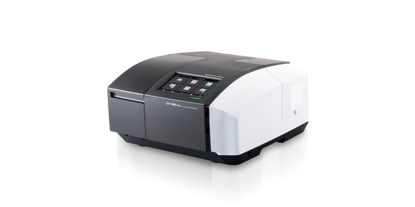
UV-1900i Plus
Experience unmatched precision and ease with UV-1900i Plus.
Featuring a refined user-friendly interface, ultra high-speed scanning, and comprehensive support functions, UV-1900i Plus ensures accurate and efficient measurements for all your needs. -
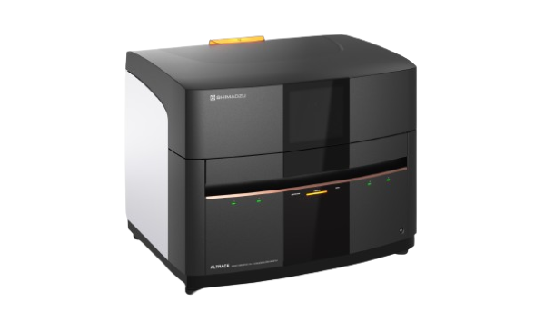
ALTRACE
Detect trace elements with ease. A combination of optical system design and Shimadzu's proprietary high-speed signal processing technology allows ALTRACE to reach new heights in terms of sensitivity.
-
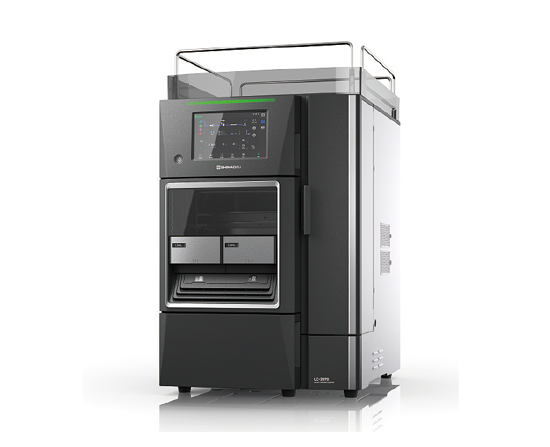
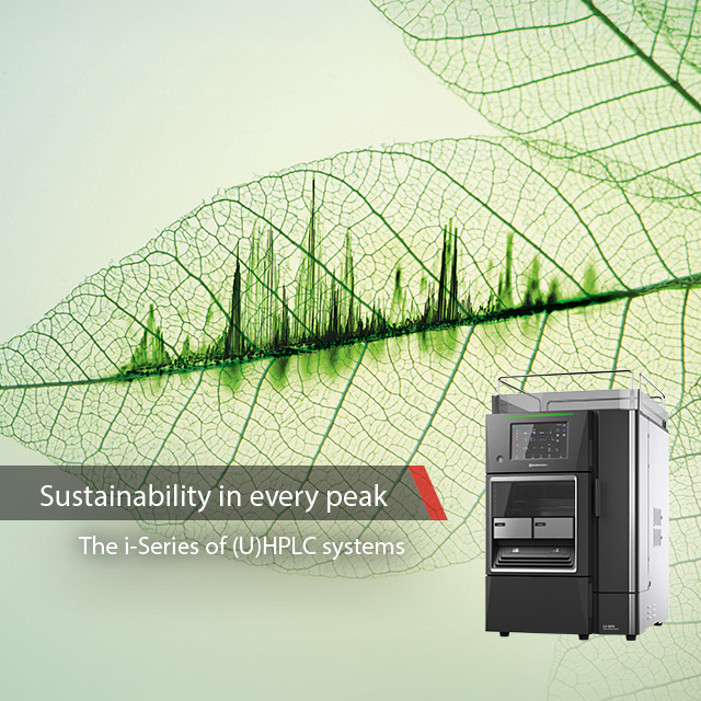
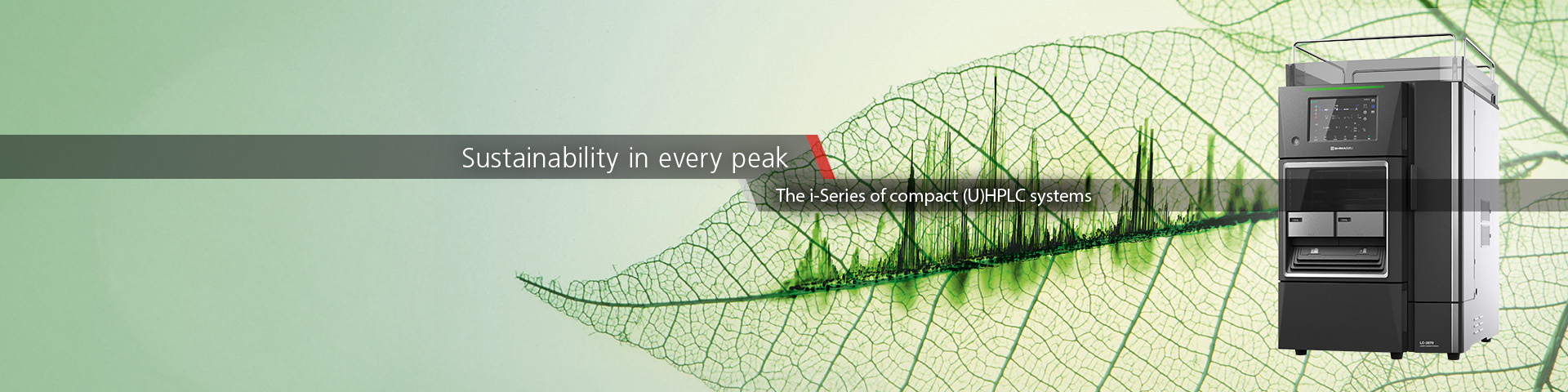
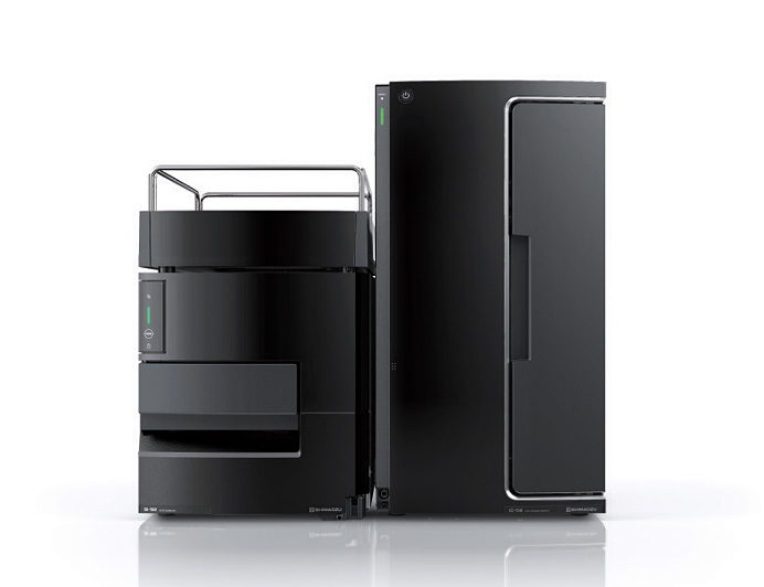
i-Series
The new i-Series integrated LC: Sustainable design. Reliable results. Uncompromising performance.